NEMA Wiring Diagram Guide for Electrical Experts
About seventy percent of the electrical malfunctions within establishments are due to inadequate wiring practices. Such data underlines the requirement of following established standards, underscoring NEMA wiring diagrams’ value for electrical experts. Through these diagrams, wiring arrangements that satisfy both functional effectiveness and highest protection criteria are delineated.
The aim of this document is to arm electrical practitioners with profound knowledge into NEMA norms. Highlighting the significance of correct electrical installations is crucial. By mastering these principles, specialists can drastically reduce the risk of accidents and guarantee they comply with safety measures backed by Installation Parts Supply. Expertise in l 14 30 plug is vital whether creating modern networks or repairing current ones, as it boosts the capability to offer secure and dependable electrical answers.
Summary Points
- NEMA wiring diagrams are vital for guaranteeing electrical security and compliance.
- Correct wiring practices can decrease electrical issues considerably.
- Understanding NEMA criteria boosts the performance of electrical setups.
- Installation Parts Supply promotes compliance with safety standards in electrical tasks.
- NEMA diagrams accommodate a wide range of uses across different sectors.
Comprehending NEMA Standards and Their Importance
NEMA criteria are pivotal in the electrical domain, guiding protection and performance meticulously. Developed by the National Electrical Manufacturers Association, they set key criteria for developing, evaluating, and marking electrical gear. This ensures uniformity and reliability across all electrical configurations, which is of great value.
Identify the NEMA Criteria?
NEMA categories vary from grades 1 up to 13. Every level defines the conditions required for electrical apparatus to operate optimally. Such as, NEMA 1 provides minimal indoor protection but is missing dust resistance. On the other hand, NEMA 4 ensures appliances is sealed, a necessity for enduring substantial water contact. Comprehending these designations is essential in selecting suitable devices.
How NEMA Criteria Are Important for Electrical Protection
The impact of NEMA standards in maintaining electrical safety is significant. They contribute greatly in minimizing shock risks, apparatus malfunctions, and fire hazards. Proper adherence to NEMA ratings enables devices to perform reliably under specific ambient conditions. For open-air usage, NEMA 3 standards provide protection against the elements, shielding the apparatus from adverse climate like rain and snow. In areas at risk of explosions, ratings like NEMA 7, 8, and 9 are essential for upholding safety.
Implementations of NEMA Standards in Wiring Diagrams
The application of NEMA standards in wiring diagrams is crucial for protected, efficient electrical systems. These drawings employ consistent symbols and layouts based on NEMA ratings, streamlining the interpretation of intricate electrical configurations. This uniformity is beneficial. It promotes clarity, uniformity, and minimizes errors, thus improving electrical protection across home and commercial environments.
NEMA Wiring Schematic Basics
NEMA wiring diagrams are vital for electrical professionals, ensuring complicated linkages clear. They detail the junctions and parts in various configurations. By understanding the elements, types, and symbols of NEMA schematics, electricians can improve their work in setups and servicing.
Constituents of NEMA Wiring Schematics
NEMA diagrams contain essential components for particular electrical installations. You’ll discover wiring endpoints, interfaces, and other hardware for safe junctions. Every piece ensures power is distributed efficiently, following safety guidelines.
Categories of NEMA Wiring Drawings
NEMA uses various drawings, like connection diagrams and circuit layouts. Schematics outline device relationships, while layouts illustrate energy distribution. Choosing the right schematic helps with troubleshooting and deployment.
Frequent Symbols Employed in NEMA Wiring Diagrams
Notations in wiring drawings are crucial for unambiguous conveyance. They depict toggles, networks, and connectors. Knowing these icons helps groups interpret drawings correctly. This ensures installations adhere to NEMA standards.
NEMA Wiring Schematic Attributes
For electrical professionals, understanding the key components of detailed electrical wiring schematics is crucial. These diagrams provide both lucidity and thoroughness, aligning installations with NEMA criteria. They demand exact annotation and proportioning to reduce installation errors. This encourages a more secure and highly efficient workplace.
Key Attributes of Accurate Electrical Wiring Drawings
Correct electrical wiring schematics are indispensable in electrical projects. They embody key features such as:
- Clarity: Schematics are required to be straightforward, lowering errors in understanding.
- Wholeness: They must include all key elements, junctions, and electrical standards.
- Standard Compliance: Following NEMA norms is imperative for ensuring safety and functionality.
- Detailed Labeling: Distinct markings on each element are fundamental for comprehension and avoiding mistakes.
- Correct Scaling: The scales should mirror the true setup to portray the system correctly.
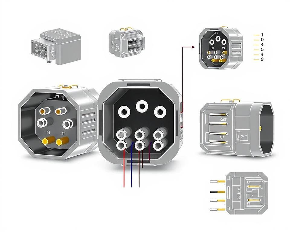
Grasping NEMA Connector Layout
The insight into NEMA coupler pinout is vital for establishing correct connections in electrical systems. Understanding of specific pin configurations upholds security and device operation. There are a variety of NEMA interfaces, designed for distinct voltage levels and amperages, covering:
| Connector Model | Current Rating | Voltage Level |
|---|---|---|
| L5-15 | 15A | 125V |
| L5-20 | 20A | 125V |
| L14-20 | 20A | 125/250V |
| L1430C | 30A | 125/250V |
| L620C | 20A | 250V |
| L1430C | 30A | 125/250V |
| L630R | 30A | 250V |
Understanding NEMA coupler configurations is crucial for secure connections, boosting effectiveness. It’s imperative to align connectors with devices correctly using rotary-lock or straight blade variants, to prevent hazards.
NEMA Device Wiring
NEMA device wiring includes various arrangements for safe electrical device interfaces. These standards ensure that equipment work together reliably, minimizing danger. Knowing the different NEMA equipment and their wiring is crucial for specialists.
Different Categories of NEMA Appliances
NEMA categorizes appliances by category based on voltage levels and amperage needs. Primary arrangements are:
- 2-Pole 2-Wire
- 2-Pole 3-Wire Grounding
- 3-Pole, 3-Wire
- 3-Pole 4-Wire Grounding
- 4-Pole 4-Wire
- 4-Pole 5-Wire Grounding
These arrangements are employed in domestic settings and manufacturing plants, handling 125V, 208V, and 480V.
NEMA Outlet Wiring Outlined
NEMA plug wiring changes to meet diverse power needs, with rotary-lock types delivering reliable connections in unstable settings. For example, the L5-15 plug operates at 15 A, common in commercial locations, whereas the L14-20 is crafted for 20 amps at 125/250 voltage.
The NEMA labeling convention assists in selecting the right plugs, spotlighting attributes like polarity and grounding. This precision guarantees that equipment operate securely.
NEMA Receptacle Wiring Instructions
Correct wiring of NEMA receptacles conforms to electrical codes and security protocols. Such as, L530R receptacles are rated for 30 amps at 125 volts, with L630R variants for 250 volts. Adequate grounding is vital to dodge electrical accidents.
Opting for approved NEMA plugs and outlets ensures secure, standard-compliant installations. It’s vital to consult authoritative protocols when installing.
NEMA Motor Wiring and Uses
NEMA motor wiring is crucial in electrical design, especially for manufacturing use. Grasping how NEMA motor arrangement works guarantees that machines are integrated for peak efficiency. Such devices, like one-phase and tri-phase models, require proper wiring to operate securely and optimally.
Introduction of NEMA Motor Wiring
Comprehending NEMA motor wiring demands familiarity of junctions and setups. Most three-phase motors offer dual-voltage, signifying they can operate at both low (208-230V) and high voltage (460V). High voltage wiring allows motors to draw less current than at low voltage. The benefits of high voltage include thinner cables for the supply, a major benefit for motors exceeding 10 HP.
While both NEMA and IEC devices are utilized in the market, NEMA models are usually more substantial and priceier than IEC ones for less than 100 HP applications. NEMA trips span size 00 to 9, appropriate for various uses. A common characteristic in NEMA trips is a Trip Class of 20, engineered to activate when a motor’s amperage surpasses 6x the Full Load Amperage in 10 seconds.
Choosing the Appropriate NEMA Motor Setup
Choosing the appropriate NEMA motor setup influences system efficiency and safety. A typical three-wire control circuit uses three wires for a power control pushbutton station, facilitating direct motor control. Frequent three-phase configurations consist of the 12 Lead Dual Voltage and 6 Lead, facilitating Wye and Delta connections.
IEC motor starters commonly feature phase failure detection, enhancing safety. They also include adjustable Fault Classes for tailored protection in low voltage levels operations. Furthermore, many units have heat protection, critical for one-phase and Dual Voltage setups.
| Configuration Type | Power Type | Current Specification | Usual Function |
|---|---|---|---|
| 12 Lead Dual Voltage | Dual Voltage (208-230V / 460V) | Dependent on motor size | Wye Start – Delta Run applications |
| 6 Lead | Single or Dual Voltage | Maximum 32A | Wye/Delta configurations |
| Single Phase | One Voltage | Dependent on adjustment (1-5A) | Applications with Two Speed, Two Winding |
| Delta Connection | High-Power Voltage | Depending on setup | Used for Current Transformers and various setups |
Final Thoughts
Grasping NEMA wiring drawings and criteria is essential for electrical professionals seeking to improve their expertise and follow electrical safety standards. These principles secure safe and high-performing electrical configurations but also avoid hazards associated with improper wiring. As discussed, following NEMA standards yields the enhanced performance of multiple NEMA appliances and systems.
For technicians, the choice of quality supplies can significantly impact the success of their projects. Installation Parts Supply offers a extensive range of wiring supplies in accordance with NEMA norms. This enables experts to obtain vital parts for meeting these key regulations. Superior resources and profound understanding of NEMA wiring drawings substantially improve system protection and effectiveness.
During electrical deployments, always put safety and accuracy above all. Gaining expertise in NEMA standards delivers the insight necessary for implementing best practices precisely. This ensures that each electrical junction made aligns with high-quality criteria.
Frequently Asked Questions
Which are NEMA wiring diagrams?
NEMA wiring schematics showcase the setups and junctions of NEMA-standard electrical devices. They follow safety and operational criteria defined by the National Electrical Manufacturers Association.
How are NEMA norms crucial for electrical security?
NEMA criteria are fundamental to defining safety and performance criteria for electrical devices. These principles assist electrical specialists reduce electrocution risks, equipment failure, and burn dangers.
What components are crucial in a NEMA wiring drawing?
Key elements in a NEMA wiring drawing include circuit configurations and linkage diagrams. These diagrams also include comprehensive labels and show the electrical system’s diverse parts precisely for setups.
Identify the varieties of NEMA wiring schematics are used?
Diverse NEMA wiring drawings address various applications, including energy distribution layouts and interconnection diagrams for components. Every design serves a distinct role in electrical installations.
What are common symbols found in NEMA wiring drawings?
Standard symbols in these schematics represent switches, interruptors, sockets, and more. Employing these symbols promotes clear communication and accurate interpretation of wiring diagrams.
Identify the key characteristics of correct electrical wiring diagrams?
Accuracy in electrical wiring drawings is marked by their clarity, comprehensiveness, and detailed annotation. They should conform to NEMA criteria to avert errors in installation.
What is a NEMA connector layout?
A NEMA connector configuration outlines electrical connections at a connector, indicating distinct pin roles. This guarantees safe and efficient linkages in electrical setups.
What are the different types of NEMA units?
NEMA units comprise various electrical receptacles and connectors, like adapters and receptacles. They are crafted for various current and voltage levels requirements to fulfill specific application requirements.
How is NEMA plug wiring configured?
NEMA plug wiring is determined by specific current and voltage levels needs, complying with safety standards and regulatory standards for various electrical uses.
Identify the recommendations are there for NEMA receptacle wiring?
Standards for connecting NEMA receptacles emphasize complying with electrical standards, ensuring accurate polarity, and choosing appropriate cable sizes. This maintains both security and functionality in electrical configurations.
What is the method to wire a NEMA motor efficiently?
To connect a NEMA motor, one must understand its defined one-phase or tri-phase configuration. Opting for the appropriate wiring approach is essential, in addition to maintaining electrical security for maximum motor efficiency.
What must be taken into account when selecting a NEMA motor configuration?
Selecting a NEMA motor configuration necessitates an analysis of the system’s voltage and current demands and functional attributes. It’s also essential to confirm alignment with current machinery for guaranteed efficiency and security.